As the scale of AI training increases, a single data center (DC) is not sufficient to deliver the required computational power. Most recent approaches to address this challenge rely on multiple data centers being co-located or geographically distributed. In a recently open-sourced feature, the NVIDIA Collective Communication Library (NCCL) is now able to communicate across multiple data centers seamlessly, taking the network topology into account to guarantee the best performance.
Below we describe the inner workings of the proposed approach, as well as the key point of attention in order to deliver the expected capabilities.
NCCL already supports multiple communicators, with each of them relying on a different network. For example, one can compose an all-reduce collective as an intra-DC reduce-scatter with the intra-DC network, followed by an all-reduce on the inter-DC network, and a final all-gather on the intra-DC network. This approach has been leveraged in the NVIDIA Nemo framework.
The goal of the proposed Cross-DC feature in NCCL is twofold. First, we guarantee the best performance in the case of multi-DC connections. And second, we enable multi-DC communication with minimal modifications to AI training workloads.
For this feature specifically, we target two connectivity scenarios (see Figure 1 below):
- Different data centers connected through a homogeneous network (typically IB or RoCE for both intra-DC and inter-DC networks).
- Data centers connected through heterogeneous networks. Typically InfiniBand (IB) or RDMA over Converged Ethernet (RoCE) for intra-DC connectivity, and TCP for inter-DC networks.
In both scenarios, we detail below how to use the cross-DC feature in NCCL, as well as some key performance considerations to keep in mind when evaluating the performance.

Network topology awareness in NCCL
Networks are exposed to NCCL through the ncclNet API. Each ncclNet corresponds to a virtual set of devices (and the associated API to interact with that set of devices) that are connected to the same network. From an NCCL perspective, two devices exposed on two different networks will be considered part of two disconnected networks. We also note that partners and network providers are free to expose the same physical network as single or multiple ncclNet structures.
This abstraction is key as it provides building blocks to support cross-DC communication. In the rest of this document, a “network” is intended as an ncclNet.
Step 1: Enabling multiple networks
To allow NCCL to use multiple networks (multiple ncclNet), one has to set NCCL_ALLNET_ENABLE=1. When NCCL_ALLNET_ENABLE is set to 1, NCCL will attempt to load all the ncclNet plugins for every communicator. The side effect is that it will disable the usage of collNet. Setting the value to 0 (default) will restore the known behavior: NCCL will only use the first successfully loaded plugin.
As mentioned earlier, NCCL assumes that devices from different networks are disconnected. While this assumption might be sufficient to infer the network topology in the scenario of heterogeneous networks, it falls short in the case of a single homogeneous network (see Figure 1). To provide a finer knowledge of the network topology, we introduce the concept of the fabric ID.
Step 2: NCCL discovers the network topology through the fabric ID
Topology awareness relies on the fabricId, which captures topology information and the connectivity between devices. Using the fabricId, NCCL queries the network topology and other path information between two network devices that are part of the same ncclNet. NCCL discovers the network topology in two steps:
- During initialization, the list of
fabricIdavailable to each rank in the communicator is exchanged. To NCCL, afabricIdis an opaque 64-bits handle. ThefabricIdis provided by the network plugin, and its exact meaning depends on the plugin implementation. - When establishing the connection, NCCL will use the newly added API to
ncclNet:getNetPath(uint64_t fabricId0, uint64_t fabricId1, ncclNetPath_t* path)to query the network connectivity. In the specific context of this feature, thepathinformation only contains the connectivity between the twofabricIds given as argument: NET_LOC_DCL0 for intra-DC connections, NET_LOC_DCL1 for cross-DC connections, and NET_LOC_DISC for disconnectedfabricIds.
Interpreting the connectivity between fabricIds is the responsibility of the network plugin. There are many ways this can be implemented, such as using 64 bits hash host names and leveraging the SLURM topology file.
In the NCCL IB plugin implementation, we have opted for a more simplistic approach. The fabricId is set through the environment variable NCCL_IB_HCA in the format device:port:fabricID. The value of fabricId should be a positive integer up to 1<<48 and is interpreted as DC_ID * MAX_RAILS + RAIL_ID, where MAX_RAILS can be set with NCCL_IB_FABRICID_MAXRAIL. If unset, each fabricId value is interpreted as a railId (i.e., fabricId = railId and dcId = 0). Devices with different RAIL_ID will be interpreted as being disconnected, regardless of their DC_ID. Devices with the same RAIL_ID and the same DC_ID will be interpreted as DCL0, and devices with the same RAIL_ID and different DC_ID will be set as DC_L1.
Step 3: Network topology guided algorithms
NCCL contains three family of algorithms: Ring, Tree (and variations like NVLSTree), and PAT. These algorithms support different flavors of collectives and communication patterns. For our work on cross-DC communication, we have focused our efforts on the more sparse communication pattern of the Ring and the Tree algorithms. All the changes detailed below are targeted toward two goals: (1) Avoid crossing the (typically slower) inter-DC links as much as possible. (2) Harness as many network devices as possible for the inter-DC connections. The latter is particularly crucial in the use case with heterogeneous networks, where the bandwidth and general performance of the inter-DC connections is significantly lower than the intra-DC connections.
Ring algorithm
To avoid multiple connection inter-DCs, we reorder the ranks first within each DC. Then, each ring is opened and the two loose ends are used to connect the DCs together. With this approach, we guarantee that the number of cross-DC connections will be 2*(nDc-1), where nDc is the number of DCs.
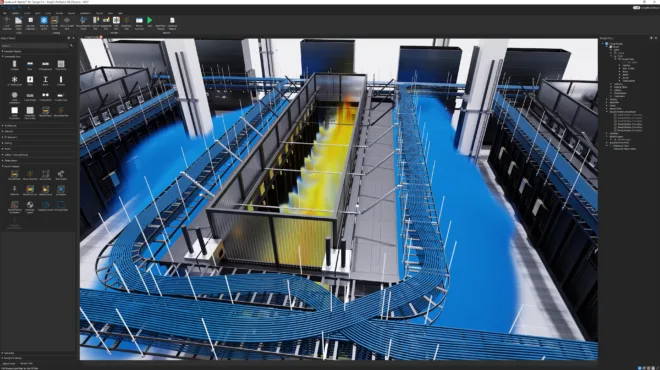
In the case of heterogeneous networks, and even with the latter approach, a single inter-DC device will be the bottleneck of the whole collective performance (see Figure 2). NCCL creates multiple rings (four in the figure), where all rings will cross the DC connection between the same set of nodes. To mitigate that effect, we introduce scattering (enabled with NCCL_SCATTER_XDC=1), where each ring will use two different nodes to cross the DC connection.
The performance gain can be substantial. For example, if the communicator contains four GPUs per node, each with a 400 Gbps HCA, a single cross-DC connection has to provide 1.6 Tbps. With the scattering enabled, the requirements on the cross-DC connection are lowered to 400 Gbps; in practice, that can be further lowered by increasing the number of channels per HCA, and therefore the number of cross-DC connections used. This explanation purposely leaves out many details, such as the selection of the number of channels and the associated protocol. Despite its inaccuracies, it provides strong intuition about the channel behavior when scattering is enabled.

Tree algorithm
Much like the ring-algorithm approach, the goal here is to avoid crossing the cross-DC connection more times than actually needed, and to allow the scattering to spread the trees across multiple devices to avoid a single device bottleneck.
We build trees first inside each of the DCs. Due to the way NCCL builds the trees, we are sure that each root has an empty child slot and an empty parent slot. This allows us to chain the roots for each tree of each DC together, in order to build a global tree covering all the DCs. The depth of the new tree will be linear in the number of DCs, and logarithmic in the number of nodes per DCs. Assuming a constant number of nodes per DC, we obtain a depth of (nDC - 1) + log2(nNodes).
The scattering of the channels is also implemented similarly to the ring algorithm. The tree roots are what actually communicate across DCs, so we scatter them amongst the available nodes. This allows NCCL to leverage more connections crossing the DCs and remove the potential bottlenecks.
Performance considerations
The quality of the connection between DCs is likely to drive the application’s overall performance. It’s important to quantify the performance of the pairwise connection, to then infer the right values for NCCL_SCATTER_XDC and NCCL_MIN/MAX_CTAS. The first will enable the scattering of the channels across multiple devices, while the second is used to control how many channels will be used by NCCL.
Below is a non-exhaustive list of the various parameters that will likely be key to reach peak performance on the cross-DC connection:
NCCL_IB_QPS_PER_CONNECTIONfor higher latency IB/RoCE connections.NCCL_NSOCKS_PERTHREADandNCCL_SOCKET_NTHREADSfor higher latency TCP connections.NCCL_SOCKET_INLINEandNCCL_SOCKET_MIN_TASKSIZEto control TCP message size and inlined data size.NCCL_BUFFSIZEto allow for larger messages to be sent by NCCL.
Summary
In a recent effort, NCCL supports seamless, collective communication spanning multiple DCs for two key connectivity scenarios. First is the homogeneous case, where a single network provides connectivity for both the inter-DC and intra-DC. Second is the heterogeneous case, where different networks (and therefore technologies) are used to connect the nodes intra-DC and inter-DC.
However, we have found the support for multiple networks to provide insufficient topology awareness to NCCL in order to deliver the best performance. To fill that gap, we introduce the fabricID, together with a new ncclNet API. This allows NCCL to query the detailed network topology and make algorithmic choices accordingly. To demonstrate our approach, we use the network topology information to optimize the rings and trees created by NCCL in order to minimize the number of cross-DC connections and improve performance.
As we develop the future of AI communication, we’re eager to gather feedback on how you use NCCL for cross-DC communication, its performance, and any weaknesses in our approach. Reach out to us on the Developer Forum, or share your feedback on Github.